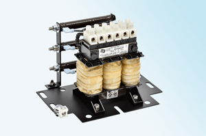
What are DV/DT Filter Reactors?
The advent of pulse width modulated (PWM) inverters with IGBT high-speed transistors, has resulted in smaller more cost effective drives and increased switching speeds. A waveform with increased harmonics at higher frequencies is the result of these much faster switching devices, often at frequencies of a few kHz.
Drives and motors often need to be separated by significant distances. For deep wells or mines, the motors are usually controlled on the surface. As a result, the distance between the drive and the motor creates long motor lead lengths. In some plant applications, the motors can withstand the harsh environment but the sensitive variable frequency drive cannot. This again results in long lead lengths to the motor.
Most manufacturers of variable frequency drives will publish a recommended maximum distance between their equipment and the motor but an application may require longer motor cables than are recommended by the VFD manufacturer. DV/DT is explained as the steep-front voltage pulses that travel down these long leads in the circuit to the motor and subsequently reverted back in a “reflective wave”. When the conductors are long enough the time for reflection matches the time for transmission resulting in a high amplitude ‘standing wave’ on the circuit. Voltage spikes of up to 2100 volts are frequently experienced for 600-volt systems, and motor winding failures can result.
A dv/dt Filter, installed in front of the motor, combines the current limiting ability of an AC line reactor plus a resistive (and/or capacitive) circuit that forms a damped, low pass filter. It provides protection for the motor by slowing the rate of voltage increase and minimizing the peak voltage that occurs at the motor terminals. The cost of a DV/DT Filter a is little more than the cost of the reactor and is best to be installed as close as possible to the VFD.

