How Harmonic Mitigating Transformers Outperform K-Rated Transformers
Abstract
The use of K-rated transformers has become a popular means of addressing harmonic related overheating problems where personal computers, telecommunications equipment, broadcasting equipment and other similar power electronics are found in high concentrations. These non-linear loads generate harmonic currents which can substantially increase transformer losses. The K-rated transformer has a more rugged design intended to prevent failure due to overheating. Unfortunately, a transformer designed simply to protect itself fails to address the other important problems associated with harmonics. Specifically, in order to prevent high voltage distortion levels from adversely affecting the equipment loads, the transformer must be capable of canceling harmonic currents and fluxes within its windings. Harmonic Mitigating Transformers (HMTs) will not only prevent transformer overheating failures but will also reduce failures in connected equipment by ensuring that IEEE Std 519 voltage distortion limits are met throughout the power distribution system.
Introduction
It is quite commonly known that harmonics generated by non-linear loads can cause serious overheating problems in standard distribution transformers. Even under much less than fully loaded conditions, transformers have been known to fail catastrophically. One of the main reasons for this is that harmonic currents will dramatically increase the eddy current losses in a transformer.
The relationship is as follows[1]:
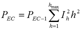
Where: PEC = total eddy current losses
PEC-1 = eddy current losses at fundamental
Ih = rms current at harmonic h
h = harmonic number
This has prompted transformer manufacturers to build more robust designs which can tolerate the additional harmonic losses. In the interest of standardization, a rating scheme has been adopted known as K-factor. K-factor reflects the increase in eddy current losses and is defined as follows[2]:
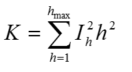
Where: Ih = rms current at harmonic h, in per unit
of rated rms current
A K-rated transformer then, is one that can be loaded to its full load rating when servicing a non-linear load with a K-factor rating no greater than the transformer’s K-rating. Standard K-factor ratings are 4, 9, 13, and 20.
It is important to note that specifying an extremely high K-rating is not necessarily a good thing. For example, a K-20 transformer is only required if the load it services is actually a load above K=13 and if it is expected to operate at or near full load rating. Specifying too high a K-rating will result in an oversized transformer which can introduce problems such as very high inrush currents, excessive current fault levels, higher core losses and a larger footprint.
The harmonics problem however, is much more than simply the overheating of electrical distribution equipment. When servicing a high concentration of non-linear loads, power distribution systems can experience a wide variety of problems, which include:
- Power factor correction capacitor failures due to overloading and / or system resonance
- Overheating cables, transformers and other distribution equipment reducing their life span
- High voltage distortion (typically in the form of flat-topping) especially when operating on weak sources, such as emergency generators or UPS systems. False tripping of circuit breakers
- Premature failure of rotating equipment (motors, generators, etc.)
-
Mis-operation or component failure in PLCs, computers or other sensitive loads
Of all the problems listed above, those resulting from high voltage distortion are often the most severe and generally the most difficult to identify.
How Harmonic Currents Create Voltage Distortion
Voltage distortion is created as harmonic currents, generated by non-linear loads, pass through the impedance of a power distribution system. Current at any frequency flowing through an impedance will result in a voltage drop in the system at that frequency. This is a simple application of Ohms Law, Vh = Ih x Zh, where:
Vh = voltage at harmonic number h
Ih = current at harmonic number h
Zh = impedance of system to harmonic h
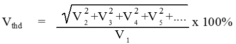
The cumulative effect of the voltage drops at each frequency produces voltage distortion. A common term used to indicate the amount of waveform distortion is Total Harmonic Distortion, or THD. THD is expressed in percent and for power systems can be applied to both voltage and current. Voltage total harmonic distortion (Vthd) is defined as a root mean square of all the harmonic voltage drops and is expressed as follows:
Current distortion is a measure of the combined effect of the various harmonic currents present
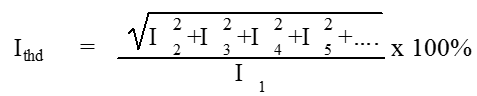
Voltage distortion then is a function of both the system impedance and the amount of harmonic current in the system. High system impedance due to long cable runs, high impedance transformers, generators, UPS systems, etc. usually causes high voltage distortion levels.
The basic relationship between current and voltage distortion can be seen by examining the waveforms themselves. A typical non-linear load, the Switch-Mode Power Supply (SMPS) is shown in Figure 1. This device draws current only during the peaks of the voltage waveform while charging the smoothing capacitor. As the applied voltage drops during the rest of the cycle, the capacitor discharges to support the load. The pulses of current which recharge the capacitor cause voltage drops which clip-off or flat-top the voltage peaks.
The Effect of Voltage Flat-topping on the Switch-mode Power Supply
How voltage flat-topping affects the operation of an SMPS is a fairly controversial topic. Many equipment manufacturers specify < 5% Vthd in their installation manuals but readily admit that many installations exceed these recommendations. IEEE Std 519 (2014) also lists 8% Vthd as a recommended limit and states, “All users limit their harmonic current emissions to reasonable values determined in an equitable manner based on the inherent ownership stake each user has in the supply system.”
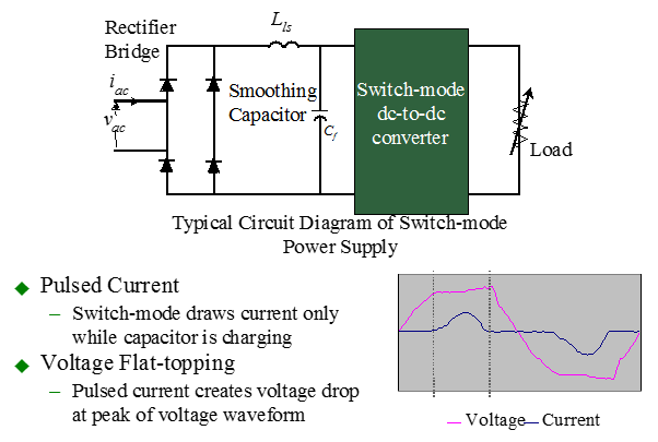
Figure 1: Relationship between pulsed current and voltage flat-topping
Often the equipment appears to operate normally but the long-term effect of exposure to a severely distorted or flattened voltage waveform is rarely considered. A drop in peak voltage will directly reduce the DC bus voltage within an SMPS. Figure 2 shows how the DC bus voltage depends directly upon the peak value of the supply voltage rather than upon its average or RMS values. During each voltage half cycle, the smoothing capacitor is charged by the voltage peak. It then discharges to support the DC voltage as the supply voltage drops to zero and returns to its peak value. The result is a DC voltage with a slight DC ripple.
When the SMPS is supplied by a sinusoidal voltage waveform, the DC bus voltage remains high. When the peak is flat-topped however, the DC bus voltage will be lowered proportionately. With a reduced DC bus voltage, the SMPS must draw more current to satisfy the power demands of the load (P = V x I). This increase in current will increase the internal I2R losses and the heat these losses produce. Components within the SMPS will then run hotter and can fail prematurely
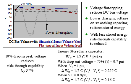
Figure 3: Voltage flat-topping reduces SMPS ride-through capability
Another negative effect of a lower peak supply voltage is reduced ride-through capability (see Figure 3). With a full peak voltage, the smoothing capacitor in the SMPS will often have enough charged energy to support the load during a brief power interruption. This can explain why a personal computer is unaffected when lighting in the area flickers during a thunderstorm or other inclement weather condition.
With a flattened voltage waveform however, the smoothing capacitor will not get fully charged. With less stored energy, this capacitor may no longer be capable of supporting a load during the full duration of a power interruption and the equipment can shutdown.
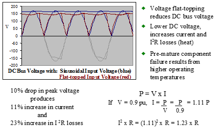
Figure 2: Voltage flat-topping lowers SMPS DC bus voltage increasing losses
The problem of voltage flat-topping becomes even more severe when weak sources such as standby generators or UPS systems are used. This is due to their higher source impedance. A generator’s impedance, for instance, can be several times higher than that of a distribution transformer. Therefore, if under normal utility power, voltage distortion at an emergency transfer switch is around 3% or 4%, it would very likely be over 10% when transferred to the standby generator during a power interruption. Often harmonic problems become obvious only when operating under emergency conditions.
High voltage distortion has been known to prevent closed transition returns to utility when power is restored after an interruption. The highly distorted voltage waveform at the generator can prevent synchronization with the normal power source. Without proper synchronization, the two sources cannot be paralleled and therefore, the load must be dropped before it can be transferred back to normal power[3].
Using HMTs to Prevent Voltage Flat-topping
Harmonic Mitigating Transformers are specially designed to reduce system voltage distortion in addition to reducing the heating effects caused by the harmonic currents. This is accomplished by cancelling load generated harmonic fluxes and currents within the transformer’s windings:
- Zero sequence harmonic currents, which include the 3rd, 9th and 15th, are prevented from circulating in the primary windings by cancelling their fluxes within the secondary windings.
- Single output HMTs are available in 2 models with differing phase shifts which when paired will induce cancellation of 5th, 7th, 17th & 19th harmonic currents upstream.
- Dual output HMTs phase shift to cancel the balanced portion of 5th, 7th, 17th & 19th harmonic currents within their secondary windings.
- Three output HMTs phase shift to cancel the balanced portion of 5th, 7th, 11th & 13th harmonic currents within their secondary windings.
- Reduction of harmonic currents in the primary windings and upstream of the HMT reduces the harmonic voltage drops and voltage distortion these drops produce.
- Losses are also reduced because the transformer and upstream distribution equipment is subjected to less harmonic current.
This means that an HMT will produce significantly less voltage distortion than a conventional or K-rated transformer when servicing similar non-linear loads. In Table 1, the performance of various HMT models is compared with a typical K-13 transformer. Included as well, is a simple dual output phase shifting transformer (Forked Wye) which is also finding application as a harmonic cancelling transformer. This transformer has dual outputs which are phase shifted by 30o to cancel the balanced 5th and 7th harmonic currents in much the same manner as the dual output HMT. The principal difference from the HMT is in the treatment of the 3rd and other triplen harmonics. Where the HMT prevents these currents from circulating in its primary windings, the Forked Wye does not. This means that voltage distortion at the 3rd harmonic will be just as high as it would be in the K-13 and conventional transformer.
Computer modeling was used to determine the voltage distortion that would appear at each transformer’s output when servicing a K-13 non-linear load of Ithd = 88%. As can be seen, the HMT transformers produced lower voltage distortion than both the K-13 and the Forked Wye. The multiple output HMTs achieved the best results by treating 5th, 7th and other higher order harmonics in addition to the triplens (3rd, 9th & 15th).
| Vthd at Transformer Output | |||
| Full load | 75% load | 50% load | |
| K-13 Transformer | 10.5% | 7.8% | 5.2% |
| Forked Wye | 7.9% | 5.9% | 3.9% |
| Single Output HMT | 6.9% | 5.2% | 3.4% |
| Dual Output HMT | 3.8% | 2.8% | 1.9% |
| Three Output HMT | 3.6% | 2.7% | 1.8% |
Table 1: Modeling of Voltage Distortion at the output of
112.5 KVA Transformers with K-13 load profile.
With this load profile, the K-13 transformer will meet the 8% Vthd limit only when loaded to less than 75%. The multiple output HMT’s, on the other hand, can be fully loaded without overly distorting the voltage waveform and the single output HMT can be loaded to 100% and won’t exceed8% Vthd.
This analysis supports the use of multiple output HMTs when a distribution system is required to service a high concentration of non-linear loads. This would include computer rooms, call centers, broadcasting studios, telecommunications sites, Internet Service Providers and hospitals to name a few. When the loading is not expected to be as severe, the single output HMT may prove to be sufficient to prevent problems from developing. In any event, the K-13 transformer is not a suitable alternative.
Case Studies Demonstrating How HMTs Will Eliminate Equipment Failure By Reducing Voltage Distortion
A Chicago area bank was troubled by consistent failures of equipment power supplies in one of its critical communications rooms. Poor power quality was considered a potential cause of the problem but it was believed that the 75 kVA UPS that serviced the load should have addressed all of the power quality needs of the equipment.
A local electrical testing company was called upon to monitor the site in an attempt to determine the cause of the equipment failures. Continuous monitoring over a period of 20 days, uncovered no troublesome impulses, surges, sags or power interruptions. An extensive review of the grounding system also produced no significant findings. During this investigation period the equipment failures continued. What the monitoring did identify however, was that the voltage downstream of the UPS was severely flat-topped with Vthd consistently above 8%.
To resolve the high voltage distortion problem, a 75 kVA, three output HMT was installed downstream of the UPS. By treating the entire spectrum of odd order harmonics (up to and including the 15th) the HMT was able to reduce the current distortion of the load from 65% to less than 10%. The direct result of this current distortion reduction was a dramatic drop in voltage distortion to less than 4%. With the installation of the HMT, power supply failures dropped from an average of 5 per month to less than 1. In time, these are expected to reduce even further as the residual effect of the long term exposure to distorted voltage begins to subside.
In another application, dual output HMTs were used to service a Test Area at a major silicon chip manufacturer. Prior to the installation of the HMTs, consistent failures in the equipment being tested were resulting in annual repairs in the amount of $200,000. The improvement in voltage distortion that accompanied the HMT installation virtually eliminated the equipment failures and the savings in maintenance costs more than justified the HMT purchase.
Conclusion
With their ability to treat both power quality and overheating harmonic concerns, Harmonic Mitigating Transformers significantly outperform their K-rated cousins. Power distribution systems designed with HMTs are capable of servicing any level of non-linear loading without suffering negative consequences. This should justify more widespread use of the HMT in applications where high concentrations of non-linear loads are found. Continued use of K-rated transformers, on the other hand, will lead to distribution systems that are incapable of being fully utilized without distorting the voltage waveform above recommended maximum levels.
References
- IEEE Emerald Book, Recommended Practice for Power and Grounding Sensitive Electronic Equipment, IEEE Std 1100-1992
- IEEE std 519-2014, Recommended Practices and Requirements for Harmonic Control in Electrical Power Systems
- Practical Guide to Quality Power for Sensitive Electronic Equipment, 2nd Edition, EC&M Books
- Taming the Rogue Wave: Techniques for Reducing Harmonic Distortion, Tony Hoevenaars, P. Eng., Published in EC&M Magazine June 1997